


Be a loving person rather than in a love relationship because relationships happen one day and disappear another day. They are flowers; in the morning they bloom, by the evening they are gone. But people find it very difficult to be a loving person, a loving soul, so they create a relationship and be fool that way that "Now I am a loving person because I am in a relationship". And the relationship may be just one of monopoly, possessiveness and exclusiveness. The relationship is needed only because love is not there. Relationship is a substitute. Become alert! Relationship destroys love, destroys the very possibility of its birth.
Thursday, 30 January 2014
Port Security
Hello everyone. How you doing. hope you all are fine. This time i am here to discuss some serious stuff with you. I will make a topology here in packet tracer to make it easy to understand for you. I will also explain scenario. So, let's get started. Here we go.

|
Device
Designation
|
Device Name
|
VLAN 1 Address
|
Subnet mask
|
|
S1
|
FC-ASW-1
|
10.0.0.2
|
255.255.255.0
|
|
PC1
|
Host
1
|
10.0.0.254
|
255.255.255.0
|
|
PC2
|
Host
2
|
10.0.0.253
|
255.255.255.0
|
|
Linksys
Internet Port
|
Intruder
|
10.0.0.252
|
255.255.255.0
|
And this is in packet tracer.

Now let's understand this step by step with configuration. Simply follow step written below.
- Referring to the topology diagram, connect the console (or rollover) cable to the console port on the switch and the other cable end to the host computer with a DB-9 or DB-25 adapter to the COM 1 port. Ensure that power has been applied to both the host computer and switch.
- Establish a console terminal session from PC1 to switch S1.
- Prepare the switch for lab configuration by ensuring that all existing VLAN and general configurations are removed.
- Remove the switch startup configuration file from NVRAM, i will show you how it works on packet tracer.
- Switch#erase startup-config
[OK]
Erase of nvram: complete
%SYS-7-NV_BLOCK_INIT: Initialized the geometry of nvram
Switch#
Step 2: Configure
the switch
configure switch and vlan 1 using configuration settings in the table above.
run following command to configure vlan 1 ip address
- interface Vlan1
- ip address 10.0.0.2 255.255.255.0
Step 3: Configure
the hosts attached
to the switch
- Configure the two PCs to use the same IP subnet for the address and mask as shown in the table.
- Connect PC1 to switch port Fa0/1 (you can choose any port)and PC2 to switch port Fa0/4. The Linksys device is not connected at this stage of the lab.
Step 4: Verify host connectivity
PC1 MAC Address: 00D0.97BE.0B84
PC2 MAC Address: 0060.2FE7.61CB
to find Mac Address you can either simply use config tab, click on fast ethernet port and you will see it.
Step 6: Determine what MAC addresses the switch has learned
Run following command. Result is show below.
PC2 MAC Address: 0060.2FE7.61CB
to find Mac Address you can either simply use config tab, click on fast ethernet port and you will see it.
Step 6: Determine what MAC addresses the switch has learned
Run following command. Result is show below.
FC-ASW-1#show mac-address-table
Mac Address Table
-------------------------------------------
Vlan Mac Address Type Ports
---- ----------- -------- -----
1 0060.2fe7.61cb DYNAMIC Fa0/4
1 00d0.97be.0b84 DYNAMIC Fa0/1
- Disconnect all PCs Ethernet cables from the switch ports.

- Ensure that the MAC address table is clear of entries. To confirm this, issue the clear mac- address-table dynamic and show mac-address-table commands. Output will be like this.
FC-ASW-1#clear mac-address-table
FC-ASW-1#show mac-address-table
Mac Address
Table
-------------------------------------------
Vlan Mac
Address Type Ports
----
----------- -------- -----
No mac entry is there in Switch. Goal achieved, let's move ahead now.
- Determine the options for setting port security on interface FastEthernet 0/4. From the global configuration mode, enter interface fastethernet 0/4.
FC-ASW-1(config)#interface fa 0/4
FC-ASW-1(config-if)#switchport mode access
FC-ASW-1(config-if)#switchport port-security
FC-ASW-1(config-if)#switchport port-security violation shutdown
FC-ASW-1(config-if)#switchport port-security mac-address sticky
Run these above commands on switch. Here remember we are implementing port security on fa 0/4 port. So if a intruder tried to access our network through port no fa 0/4. Blastt!!, haha i mean his pc will be shut down automatically. Command responsible for this is switchport port-security violation shutdown.
FC-ASW-1#show port-security interface fastethernet 0/4

Everything going good. Move on.
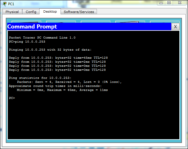
- Connect PC1 to switch port Fa0/1 and PC2 to switch port Fa0/4. b. From the command prompt ping from PC1 to PC2.

we can say if we will ping from pc2 to pc1 it will be successfull.As ping from pc1 to pc2 is successfull shown above.
- From the console terminal session, issue the show mac-address-table command.

Have you noticed something. Port fa 0/4 has turned into from dynamic to static. because we have applied port security on that port. PC having mac address 00d0.97be.0b84 can only connect to fa 0/4, no other PC can connect to it. That's what does static implies.
Now let's check Fast ethernet port 0/4 status.

You can see the changes that were not there. Violation mode, security ans so on. Run the following command to Confirm fa 0/4 status.
FastEthernet0/4 is up, line protocol is up (connected)
Hardware is Lance, address is 00d0.ba97.db04 (bia 00d0.ba97.db04)
BW 100000 Kbit, DLY 1000 usec,
reliability 255/255, txload 1/255, rxload 1/255
Encapsulation ARPA, loopback not set
So, everything is all right. Port is up and line protocol is also up. let's move ahead.
Step 9: Test the port security
- First of all Disconnect PC2 from Fa0/4
- Connect PC2 to the Linksys using one of the ports on the Linksys LAN switch.
- Use the Basic Setup tab to configure the Internet IP address on the Linksys device to the address and mask, as shown in the table.

- Configure PC2 to get an IP address using DHCP. Verify that PC2 receives an IP address from the

- Connect the Internet port on the Linksys to Fa0/4.
Done with it. Now let's test it.
Ping PC1 to PC2. What you see. Hmm, Ping is not successful. when you will try to ping from PC2 to PC1 through linksys router, Link will turn down into red color indicating that PC2 will be shut down. Because PC2 is being accessed by intruder is attached to fa 0/4 port. Where PC2 must be attached to get access.Run these commands:
- FC-ASW-1#show mac-address-table
Mac Address Table
-------------------------------------------
Vlan Mac Address Type Ports
---- ----------- -------- -----
- FC-ASW-1#show interface fastethernet 0/4
- FC-ASW-1#show port-security interface fa 0/4
Port Security : Enabled
Port Status : Secure-shutdown
Violation Mode : Shutdown
Aging Time : 0 mins
Aging Type : Absolute
SecureStatic Address Aging : Disabled
Maximum MAC Addresses : 1
Total MAC Addresses : 1
Configured MAC Addresses : 0
Sticky MAC Addresses : 1
Last Source Address:Vlan : 0040.0B7D.1A01:1
Security Violation Count : 1
All these results shows us that there is violation and due to it port has been shout down.
That's it we are done with this tutorial. I have packet tracer file with me. if you need it please Mention it below in the comments. i will email it.
Subscribe to:
Post Comments (Atom)
Popular Posts
-
OPEN MS-DOS Source Code Early tech fans might remember the good 'ol days of Microsoft MS-DOS, the company's first operating s...
-
 Hello folks, How are you all. Today I'm here to bring you on of the most amazing hacking news or trick you can say. So let's begin ...
 -
 Hello there, Do you know when you submit a page on stumble upon then what happen. Under which process it goes?. Um, No. Oh, You need not t...
 -
Medium Medium, the blogging platform created by Twitter co-founder Evan Williams, launched its first mobile app this week. The app let...
-
 Hello, there again some poetry. This time i wrote this for someone who is close to my heart. Not close indeed very much close to me. I...
 -
Hello there, Welcome to our blog. How you all are, Hope you all doing great. On our blog you will find support for tech, hacking and so...
-
Google has begun a Glass at Work initiative, asking businesses how they're working with Glass, and the kinds of applications they...
-
Hello folks, this is my first post. M gonna explain about Pat and will give configuration for it with an example below. Port Address...
0 comments:
Post a Comment